
A GPS tracker can be configured perfectly and still deliver poor data because of where it sits. A unit wedged under a metal floor plate reports positions that jump across the road. A unit tucked beside the fuse box is the first thing a dishonest driver finds. A unit cable-tied loosely behind a panel records harsh braking every time the van crosses a speed bump. GPS tracker placement decides how much of the device’s capability actually reaches the fleet.
This article explains where to place a GPS tracker inside fleet vehicles and why each location works or fails. It covers what the unit needs from its location, the cabin spots that usually work and the ones to avoid, layouts for cars, vans, and heavy trucks, placement that reduces tampering, a fleet-wide planning sequence, and the mistakes installers see most often.
What a GPS tracker needs from its location
Every placement decision balances five needs: a view of the sky, a usable cellular signal, clean power and wiring, firm mounting, and protection from tampering. A location that serves four of them and fails the fifth will show up later as bad data or a missing device.
Sky view for satellite positioning
The Tracom ST100 calculates position with GPS, GLONASS, SBAS, QZSS, and AGPS, with accuracy within a 2-meter radius when the unit has a clear view of open sky. Metal blocks satellite signals and causes inaccurate or delayed positions. Satellite signals should reach the unit through glass, plastic, or fabric, never through a steel roof, floor, or bulkhead. Heat-reflective window films can also weaken reception, so check the windshield before choosing a spot behind it.
Cellular signal for data transfer
The ST100 sends data over a 2G, 3G, or 4G SIM. A location buried deep inside metal structures weakens the cellular signal as well as the satellite one. When the network does drop, the device applies its rules without internet access and stores up to one week of data on the device, but good placement keeps those gaps for genuine coverage problems, not self-inflicted ones.
The tracking device behind every record
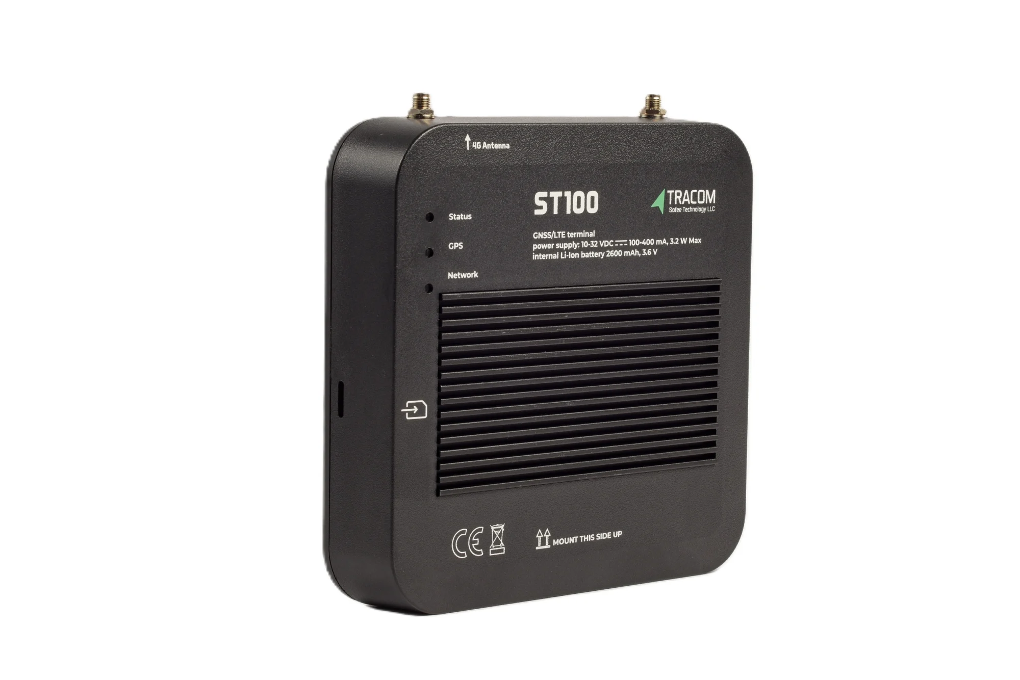
- GPS, GLONASS, SBAS, QZSS and AGPS positioning
- Location accuracy within a 2-meter radius
- 2G/3G/4G SIM support
- 12 digital, 4 analog and 5 AD inputs, 2 digital outputs
- 5 RS232 ports, USB, UART, 1-Wire and OBD II CAN
Stable power and wiring
The unit’s power and input wiring decide whether it reports reliably and whether events mean what they say. The ST100 has 12 digital inputs, 4 analog inputs, 5 AD inputs, RS232 ports, a 1-wire interface, and an OBD-II CAN interface, so the chosen location must leave a short, protected route for every cable the fleet plans to connect. Keep the unit and its wiring clear of airbag modules and their harnesses, connect power through a fused circuit, and follow the vehicle manufacturer’s wiring guidance. The guide to GPS tracker wiring covers power, ground, and ignition connections in detail.
Firm mounting for the G-sensor
The ST100’s built-in G-sensor detects acceleration, harsh braking, sudden impacts, and sharp movements. A unit that can shift or rattle produces false harsh events, so it should be fixed firmly to a rigid part of the vehicle structure, in a fixed orientation, with brackets or ties that do not loosen with vibration. A firm mount also keeps harsh event and impact records credible when a driver disputes an event.
What placement does not decide
A good location does not automatically determine whether the installation is safe for the vehicle’s electrical system, whether it affects the warranty, or which events the fleet should act on. Tracom supplies the GPS device, local rule logic, event data, and configuration layer. The installer, the fleet, and its connected business software remain responsible for the installation standard, the operational meaning of each event, and the response.
Where to place a GPS tracker in a fleet vehicle
Most commercial installations place the unit inside the cabin, behind trim, where it is protected from weather and out of the driver’s sight. The table below compares the locations installers use most often.

| Location | Best fit | Main risk | Placement rule |
|---|---|---|---|
| Behind the upper dashboard | Cars, pickups, vans | Metal brackets nearby | Under plastic trim, not metal |
| Behind the instrument cluster | Most vehicle types | Crowded wiring | Keep clear of airbag harnesses |
| Inside the A-pillar or headliner trim | Vans and trucks with metal dashboards | Trim removed during repairs | Record the location for workshops |
| Behind side or rear interior panels | Vans and buses | Weaker sky view | Test signal before closing the panel |
Cabin locations that usually work
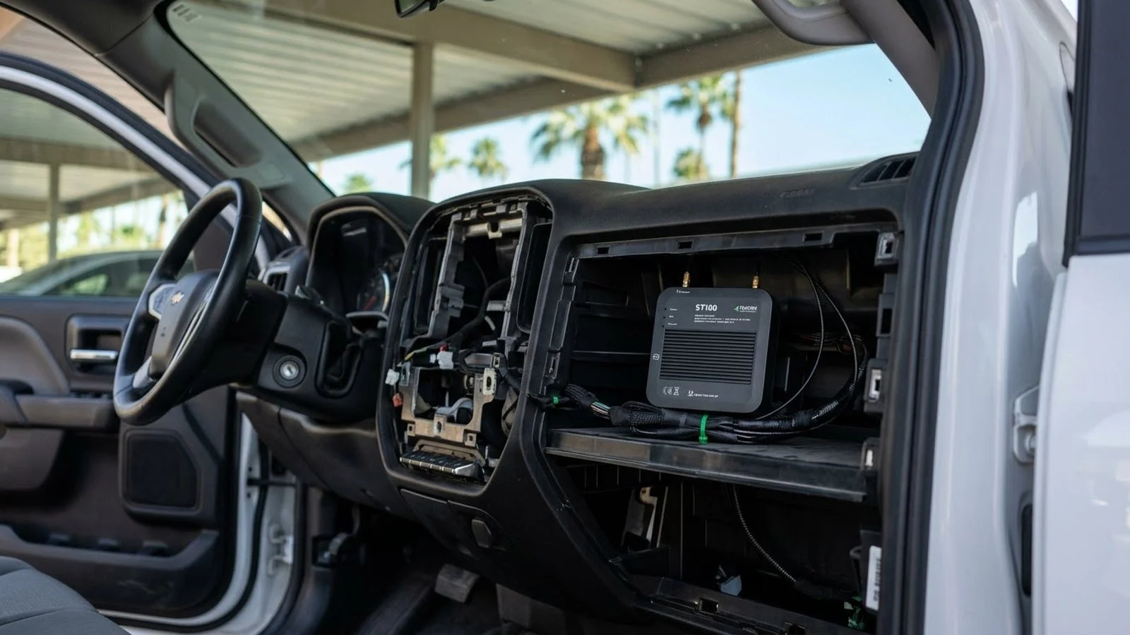
Behind the upper dashboard is the most common choice because the windshield above gives a clear view of the sky and the space is hidden from the driver. Behind the instrument cluster works well when the dashboard top is crowded, as long as the unit stays clear of airbag modules. In vans and trucks with metal dashboard frames, the headliner or A-pillar trim near the windshield can give better reception.
Locations to avoid
Some locations look convenient and cause problems later:
- Under metal floor plates or seats with steel frames, because the metal blocks satellite and cellular signals.
- Inside the engine bay, because heat, water, and vibration there are harsher than in the cabin.
- In the glove box or any compartment drivers open daily, because the unit is easy to find and remove.
- Directly against heaters, air-conditioning ducts, or audio amplifiers, because they add heat and electrical noise.
- Next to the OBD-II port without concealment, because a visible tracker is an easy target for removal.
In the Gulf summer, a dashboard top under direct sun can get much hotter than the cabin air, so keep the unit behind trim and away from the glass itself. The guide to GPS trackers in extreme heat explains how to plan installations for GCC conditions.
Read also: GPS Tracker with Engine Cut-Off: How Immobilization Works Safely
Placement by vehicle type
Vehicle layouts differ more than most rollout plans assume. One standard position for every vehicle type usually means poor results in at least one group.

Cars and pickups
Sedans, SUVs, and pickups usually take the unit behind the upper dashboard or the instrument cluster. Their windshields give good sky view, and short cable runs to power and ignition keep the wiring simple. Pickups used on job sites should have the wiring protected from dust and kept off the cabin floor, where mud and water collect.
Vans and delivery vehicles
Panel vans often have metal partitions behind the driver and long metal roofs. The windshield area remains the most suitable spot, either behind the dashboard top or in the headliner trim. Avoid the cargo area entirely, because the unit loses sky view behind the partition and loaders may damage it.
Heavy trucks and tankers
Truck cabs offer more space but also more metal, and many fleets need several inputs wired, such as ignition and equipment signals. Choose a location behind the dashboard or overhead console with a short route to the cab’s main wiring, and keep the unit away from the battery compartment and the exhaust side of the cab. The guide to truck tracking devices covers the wider selection questions for heavy vehicles.
Placement that reduces tampering
A tracker that a driver can reach in thirty seconds is a tracker that will eventually be unplugged. Placement is the first layer of protection, and alerts are the second.
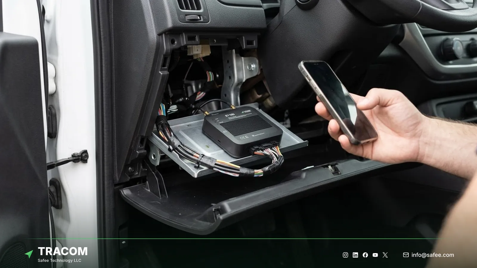
Concealment and access
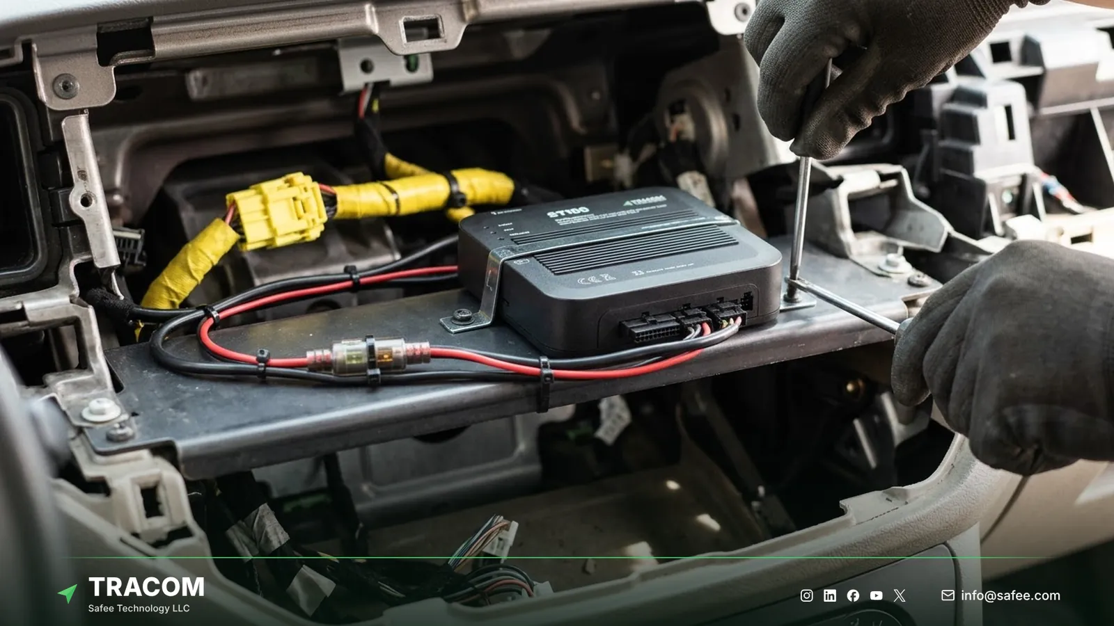
Hide the unit behind trim that needs tools to remove, and route the cables along existing harnesses so they look like factory wiring. Avoid labels on the outside of the unit, and record each vehicle’s placement in the fleet’s installation sheet so workshops know where it is before they remove panels. Use the same principle across a vehicle group, but vary the exact position slightly where drivers share tips about where trackers sit. The guide to a hidden GPS tracker for company vehicles covers testing, installation records, and driver policy for a full concealed rollout.
What the tamper alert adds
Concealment slows removal, and detection speeds up the response. The ST100 sends a tamper alert when someone attempts to remove or interfere with the device, and up to 1,000 driver access keys with immobilization limit vehicle operation to authorized drivers. Neither measure prevents every theft, but together they shorten the time between an attempt and the fleet’s response. The guide to GPS tracker tamper alerts explains the common tampering methods and how to respond to each alert.
Steps to plan placement across the fleet
A placement plan written before installation day prevents most of the problems that surface weeks later.
- Group vehicles by make, model, and body type, because each group needs its own placement standard.
- Inspect one vehicle per group with the installer, and mark the unit position, cable routes, and power source.
- List every signal to connect per group, such as ignition or equipment switches, and confirm the input for each one.
- Install the first unit, then test sky view, cellular signal, and G-sensor readings with the vehicle parked and on a short drive.
- Photograph the final position and cable routes, and save them in the installation sheet for that vehicle group.
- Install the rest of the group to the same standard, and recheck a sample of vehicles after the first weeks of operation.
- Push the group’s configuration from the SCMS portal over the air, so installers do not need to change settings inside the vehicle.
For a fleet with several vehicle types and sites, share your vehicle list and the signals you plan to connect, and talk to a Tracom specialist about a placement standard for each group. The choice between installation methods is covered separately in the guide to fleet GPS tracker installation.
Read also: Does a GPS Tracker Drain the Vehicle Battery? What Really Happens
Common placement mistakes
Most placement problems trace back to a few repeated decisions. These are the ones to avoid.
| Mistake | Operational consequence |
|---|---|
| Unit mounted under metal | Positions jump and arrivals are recorded late |
| Unit fixed loosely with one tie | False harsh braking events reach driver scores |
| Visible unit near the OBD-II port | Devices are unplugged and trips go missing |
| One placement for every vehicle type | One vehicle group reports poor data |
| Wiring routed near airbag modules | Safety risk and failed workshop inspections |
| No record of the placement | Workshops damage or remove units during repairs |
| No signal test before closing panels | Weak reception is found only after rollout |
Weak reception from poor placement also affects what dispatch sees, as explained in the guide to live fleet tracking.
Where Tracom hardware goes in each vehicle
At Tracom, we supply the Tracom ST100, which applies fleet rules inside the vehicle and is managed remotely, so after a correct installation most configuration changes happen without opening the trim. Many fleets also fit one or more Tracom accessories, and each one has its own placement rule. The table lists the hardware an installer places and what to agree first.
| Need | ST100 feature, input, or accessory | Confirm with the Tracom team |
|---|---|---|
| Position and rules | ST100 behind trim with sky view, G-sensor firmly mounted | Mounting position per vehicle model |
| Removal detection | Tamper alert | Concealment and power wiring route |
| Driver identification | Driver key reader within the driver’s reach | Reader position and immobilization wiring |
| Emergency alerts | Panic button reachable from the driver seat | Button position per cabin layout |
| Fuel monitoring | Fuel level sensor in the tank | Sensor type and fit per tank |
| Cold cargo | Temperature sensor in the cargo body | Sensor type and cable route to the cab |
| Video | Tracom M1N MDVR in a protected cabin position | Recorder location and camera options |
The ST100 offers 12 digital inputs, 4 analog inputs, 5 AD inputs, 2 digital outputs, 2 pulse counters, RS232, USB, UART, 1-wire, and an OBD-II CAN interface, so plan a cable route for every accessory before closing the panels. It is configured through the SCMS portal with XML and KML/KMLO files, OTA firmware updates, and SMS commands. You can compare device categories in the guide to types of GPS fleet tracking devices. The mounting position and signals for each vehicle model should be confirmed during solution design. Request a device recommendation with your vehicle models, and our team will help define the placement standard for each group.
Conclusion
Good GPS tracker placement gives the device a clear sky view, a usable signal, clean wiring, a firm mount, and enough concealment to slow tampering. A unit that fails any of these produces data the fleet cannot trust, however well the rules are configured.
Tracom provides the GPS device, in-vehicle rules, tamper alerts, and remote configuration that keep tracking working once the unit is correctly installed. Share your vehicle models, the signals and accessories you plan to connect, and your installation partners, and talk to Tracom about ST100 devices for your fleet or your customers’ fleets, with a placement standard for each vehicle group.
Frequently asked questions
Where should a GPS tracker go in a vehicle?
Usually behind the upper dashboard or the instrument cluster, inside the cabin. These locations give the unit a view of the sky through the windshield, keep the unit hidden from the driver, and allow short cable runs to power. Vehicles with metal dashboard frames may need the headliner or A-pillar trim instead.
Can a GPS tracker work when it is hidden?
Yes. A tracker hidden behind plastic trim, fabric, or glass can still receive satellite and cellular signals. What it cannot do well is work under metal, such as steel floor plates or seat frames, which block signals and cause inaccurate or delayed positions. Test reception before closing any panel.
Does placement affect harsh braking alerts?
Yes. The ST100’s G-sensor measures the vehicle’s movement, so a loosely mounted unit can register its own rattling as harsh braking or sharp movement. Fixing the unit firmly to a rigid part of the structure, in a fixed orientation, keeps G-sensor events accurate and fair to drivers.
Should a GPS tracker be installed in the engine bay?
No, not as a default choice. The engine bay exposes the unit to more heat, water, and vibration than the cabin, and the metal hood blocks sky view. Install inside the cabin unless the Tracom team and your installer confirm a different location for a specific vehicle model.
Is Tracom responsible for how the tracker is installed?
No. Tracom provides the device, in-vehicle rules, event data, and remote configuration. The installer and your fleet decide the mounting position, wiring standard, and compliance with the vehicle manufacturer’s guidance, and your organization decides how each event from the device is reviewed and acted on.
Choose the right tracker for every vehicle
Tell us your vehicle types and what you need to monitor. A Tracom device specialist will reply by email with a recommended ST100 setup and accessories.
Usually replies within one business day • No sales spam
Your details are used only to respond to your request. Privacy Policy